Orbit correction
After misalignments are planted (from ERROR_* cards or per-seed
randomization in an ErrorStudy), the residual orbit must usually
be corrected before the post-error tracking gives a useful answer.
HELIX's correction driver mirrors TraceWin's ADJUST_STEERER
semantics: scan the lattice for adjustment cards, pair each with a
BPM (via the card's diag_n) and a steerer (the next Steerer
after the card by default), build a finite-difference response
matrix, solve for kicks that null the BPM readings.
TL;DR (TraceWin users)
| TraceWin | HELIX | |
|---|---|---|
| Correction card | ADJUST_STEERER N max first_step |
parsed → AdjustSteerer(diag_n=N, vmax=max, first_step=first_step) |
| Card pairs with | next STEERER after the card |
same (override via card.target_name) |
diag_n resolves to |
the N-th DIAG_POSITION |
the N-th Marker(is_bpm=True) |
max units |
T (peak field) | T·m (integrated kick) — see note below |
| Method when #steerers == #BPMs | direct linear solve | one_to_one |
| Method when #steerers != #BPMs | optimization | svd (truncated pseudoinverse) |
Units of vmax
TraceWin's max is the magnet's peak field strength. HELIX
Steerer is a zero-length thin element whose state is the
integrated kick bx_l / by_l in T·m. We therefore interpret
max directly as a clip on |bx_l| / |by_l|. Numerically
equivalent for any 1 m-equivalent steerer; if you supplied a peak
field expecting it to multiply by some implicit length, rescale
the value yourself before relying on the clip.
Steering to DIAG_POSITION targets ("matched with diagnostics")
Every entry point accepts a targets option (default None =
the historical flatten-to-zero, bit-identical):
targets="deck"— steer each BPM onto theDIAG_POSITION N X Y [dm]operands the deck carries (e.g. a recorded machine orbit). A1e50operand leaves that plane free; a runtime target file (Lattice tab → BPM targets…) overrides the card values.targets={"BPM_1": (0.5, -0.3), ...}— explicit set-points (mm).
Readings are always computed by MP tracking — targets only shift
the set-point the solve drives the reading onto. For decks whose
ADJUST N v cards bind steerers, use the dedicated driver:
from linac_gen.errors.correction import apply_diagnostic_matching
res = apply_diagnostic_matching(lattice, beam_factory)   # SVD, deck targets
This is TraceWin's own special case ("when the number of steerers
corresponds to the number of BPMs … the resolution of the system is
directly made by a matrix inversion"). Decks whose ADJUST cards bind
quad gradients (PIP-II fnalscl: 28 of 30 cards) are a nonlinear
fit — use the matching engine instead (match(...) with either cost
solver; the DIAG targets appear there as auto-generated position
constraints). Per-sample study correction inherits the option through
ErrorStudy.enable_correction(..., targets="deck").
Reading backends. Every correction entry point accepts
reading_backend="mp" (default — track a fresh multi-particle beam
per reading, legacy behaviour) or reading_backend="envelope" plus
beam_config= (a BeamConfig): envelope results carry the beam
centroid, so BPM readings come from a seconds-fast, deterministic
envelope pass — no sampling noise, so n_iter=1 usually converges
and the solve lands exactly on the targets. bpm_noise still
applies (it models the diagnostic, not the beam). In Monte-Carlo
studies the envelope backend cuts per-seed correction cost by roughly
an order of magnitude
(enable_correction(..., reading_backend="envelope") or the
Errors-tab "Readings" selector).
Quick start
Three ways to invoke correction: GUI standalone, GUI inside an error study, and Python. All three produce the same result for the same lattice — pick whichever fits the workflow you're in.
Path A — GUI standalone (Lattice tab → "Correct orbit")
Use when the lattice is already loaded and you want a one-shot correction pass on a fixed misalignment scenario.
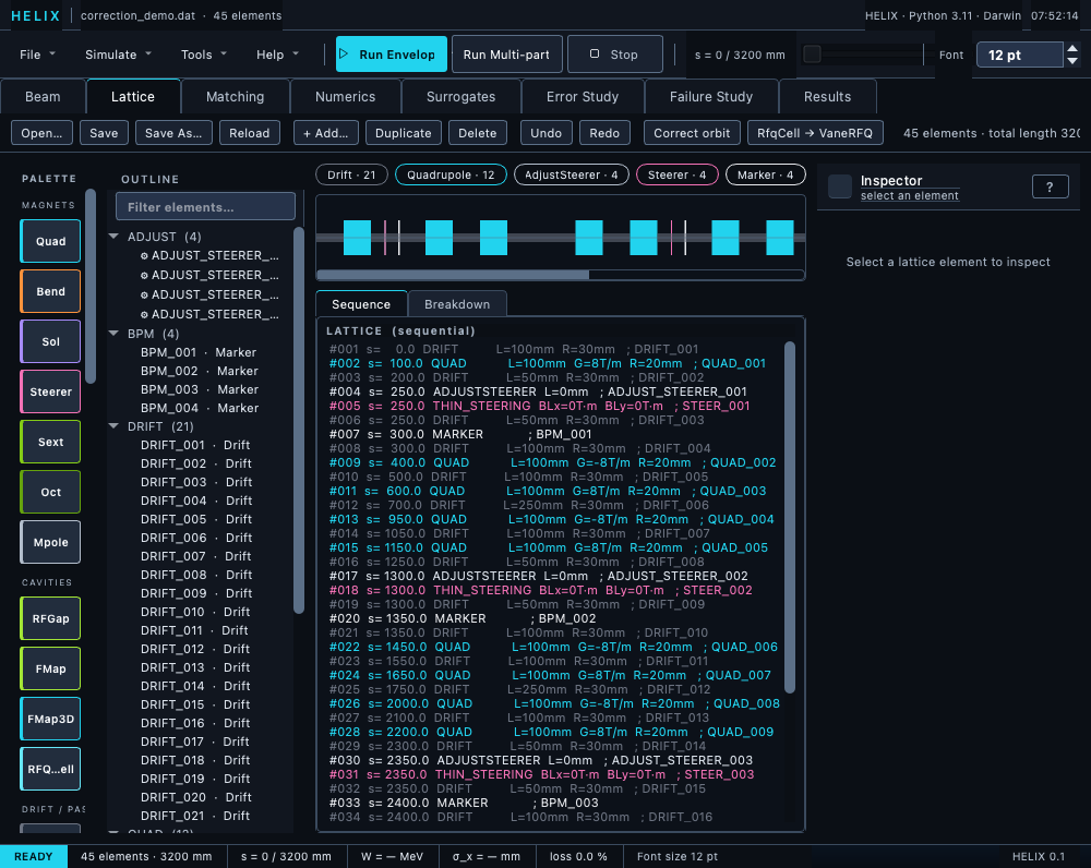
Lattice tab toolbar — "Correct orbit" sits between the Undo/Redo buttons and the right-side lattice summary text.
-
Launch the GUI.
-
Lattice tab → Open… Pick a lattice with steerers + BPMs (or a TraceWin .dat with
ADJUST_STEERERcards). The bundledexamples/correction_demo/correction_demo.datis the reference. -
Beam tab → set species, energy, frequency to match the lattice (5 MeV proton at 352.21 MHz for the demo).
-
Lattice tab → "Correct orbit" toolbar button. HELIX runs
run_correction_from_lattice(..., n_iter=5, tol_mm=0.05)on a worker thread. After ~1 s a summary dialog reports:- Method picked (
one_to_oneif #steerers == #BPMs cleanly, elsesvd). - Number of steerer/BPM pairs.
- Status — see the dead-beam contract for the vocabulary.
- RMS BPM reading at the first and final pass, and the transmission per pass.
- Each steerer's applied
bx_l/by_lin T·m.
If the computed kicks would LOSE the beam (
Status: beam_lost), the dialog becomes a warning naming the element where the transmission reached 0 % and no kicks are applied — the steerers keep their previous values and nothing lands on the undo stack. - Method picked (
-
Inspect the result. The steerers are mutated in place, so the timeline + Inspector show the corrected
bx_l/by_lvalues immediately. Any subsequent envelope or MP run uses the corrected steerers.
The standalone button refuses to run when the lattice has no
ADJUST_STEERER cards AND no is_bpm markers AND no
BPM_*/STEER_* name matches — it tells you to add steerers
+ BPMs first.
Path B — GUI inside a Monte-Carlo error study (Error Study tab)
Use when you're randomising errors per seed and want each seed's orbit corrected before tracking, so the recorded centroid trace shows the post-correction state.
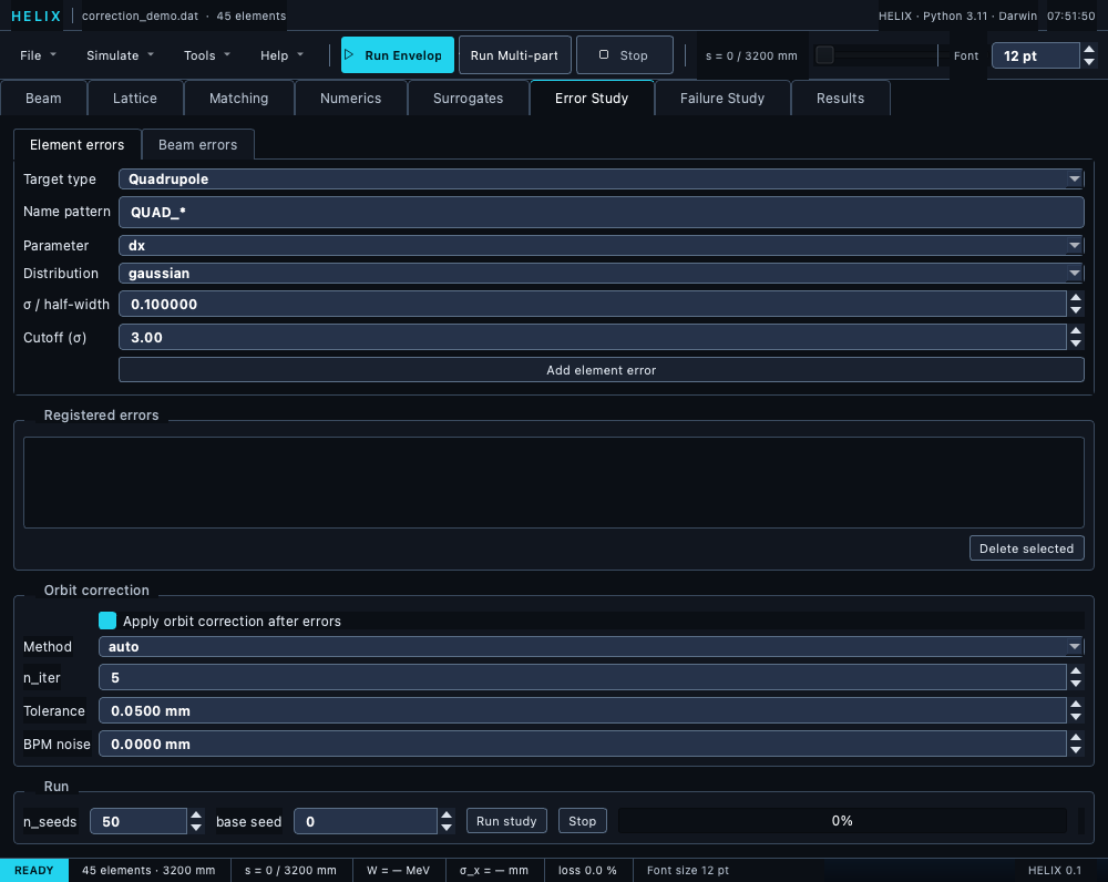
Error Study tab — element-error form at the top, registered-errors list, Orbit correction group with Method / n_iter / Tolerance / BPM-noise (children disable when the checkbox is off), Run group with n_seeds + progress bar at the bottom.
-
Lattice tab → Open… the lattice.
-
Beam tab → confirm beam settings.
-
Error Study tab → element form (top section): register one or more error specs. For a quad-misalignment study:
- Target type: Quadrupole
- Name pattern:
QUAD_*(or whatever matches the elements you want to misalign) - Parameter:
dx - Distribution: gaussian
- σ: e.g. 0.1 mm
- Cutoff: 3.0
- Add element error. Repeat for
dyif you want both planes.
-
Error Study tab → Orbit correction group (between the registered-errors list and the Run button):
- Tick Apply orbit correction after errors.
- Method: auto (recommended), or force one_to_one or svd.
- n_iter: 5 (default).
- Tolerance: 0.05 mm.
- BPM noise: 0.0 mm (raise to 0.01–0.1 mm to model finite BPM resolution).
-
Run group → set n_seeds (start with 20 to feel it out) → Run study. The progress bar advances as each seed (a) gets random errors applied, (b) runs the corrector, (c) tracks; the corrector log entry is stored on the result bag.
-
Results tab → the centroid ensemble plots show the post-correction state. Without the checkbox you'd see the un-corrected orbit; with it the centroid stays near zero for every seed.
-
Programmatic access to per-seed kicks:
res = state.error_study_results for seed in range(res.n_seeds): kicks = res.corrected_kicks(seed) # dict: { steerer_name -> {"bx_l": float, "by_l": float} } hist = res.correction_history(seed) # list: [ {"iter": k, "rms_orbit_mm": x, "n_saturated": m, # "n_dead_bpms": d, "transmission_pct": t, # "beam_lost_at": name, "stop_reason": r}, ... ] status = res.correction_status(seed) # "converged" | "saturated" | "max_iter" | "beam_lost" | "none"res.n_correction_beam_lostcounts the seeds whose correction lost the beam; the study emits aUserWarning(and the Error- Study tab's status line says so) whenever it is non-zero — those seeds track a dead beam.
Path C — Python script
The same code paths the GUI uses are public API:
from linac_gen.errors.correction import run_correction_from_lattice
from linac_gen.io.tracewin_parser import parse_tracewin
from linac_gen.distributions.factory import create_beam
from linac_gen.core.config import BeamConfig

lattice, _ = parse_tracewin("examples/correction_demo/correction_demo.dat")
beam_cfg = BeamConfig(species="proton", energy=5.0, frequency=352.21,
                      current=0.0, n_particles=2000,
                      distribution="gaussian", cutoff=4.0,
                      emit_nx=0.05, emit_ny=0.05, emit_z=0.10,
                      alpha_x=0.0, beta_x=2.0,
                      alpha_y=0.0, beta_y=2.0,
                      alpha_z=0.0, beta_z=1.0)

result = run_correction_from_lattice(
    lattice,
    beam_factory=lambda: create_beam(beam_cfg, seed=0),
    n_iter=5, tol_mm=0.05, history=True,
)
print(f"method={result['method']}, n_pairs={result['n_pairs']}")
for steerer, kicks in result["kicks"].items():
    print(f"  {steerer}: bx_l={kicks['bx_l']:+.3e}  by_l={kicks['by_l']:+.3e}")
For per-seed correction inside a Monte-Carlo error study without the GUI:
from linac_gen.errors.error_model import ErrorStudy

study = ErrorStudy(lattice, beam_cfg, n_seeds=50)
study.add_error("QUAD_*", "dx", sigma=0.1, distribution="gaussian", cutoff=3.0)
study.enable_correction(method="svd", n_iter=5, tol_mm=0.05)
results = study.run()

for seed in range(results.n_seeds):
    print(seed, results.corrected_kicks(seed))
What the numbers should look like
For the demo lattice with 0.2 mm RMS quadrupole misalignments applied to all 12 quads:
| State | RMS BPM reading |
|---|---|
| Nominal (no errors) | ~0.03 mm (just the particle-noise floor) |
| After errors | ~0.5 mm |
| After correction | < 0.001 mm |
For the standalone Lattice-tab button on this scenario (pre- correction RMS BPM reading 0.5085 mm — the demo script prints it), the summary dialog reads:
Method: one_to_one
Steerer/BPM pairs: 4
Status: converged
RMS orbit error vs targets, iter 1: 0.0000 mm
RMS orbit error vs targets, final:  0.0000 mm
Transmission per pass: 100.0 %
(target-less BPMs steer to zero)

Applied kicks:
  STEER_001: bx_l=+9.284e-05  by_l=+1.208e-04
  STEER_002: bx_l=-1.533e-03  by_l=-1.134e-03
  STEER_003: bx_l=+4.845e-03  by_l=+3.315e-03
  STEER_004: bx_l=-8.153e-03  by_l=-4.406e-03
All four steerers receive a non-zero kick: each pair's BPM sits directly after its cell's defocusing quad (a 250 mm lever arm through the quad), so every pair sees — and nulls — its own share of the misalignment orbit, and the transmission stays 100 % through every pass.
Troubleshooting
If correction makes the orbit worse, the most likely cause is vmax saturation — one steerer is hitting its T·m limit and the residual propagates to downstream BPMs. Two fixes:
- Bump the partner
ADJUST_STEERERmaxfield (e.g. from 0.01 to 0.05 T·m) in the .dat. - Switch the GUI method to
svd(handles tight FODO geometry better thanone_to_onebecause it distributes the correction across all steerers simultaneously).
The per-iteration history log includes n_saturated —
when it stays > 0 across iterations the corrector has hit the
limit.
If the status is beam_lost, the corrector's own kick drove
the beam into an aperture: a BPM too close to its steerer (a short
drift-only lever arm) demands a huge kick to null a small offset —
the original demo deck's 50 mm steerer→BPM spacing asked for
−35 mrad and scraped the beam two cells later. Move the BPM
farther downstream (through a quad), relax the target, or switch
to SVD; the warning names the element where the transmission
reached zero.
Auto-correction-on-load
The GUI has a project-file setting auto_correction_mode with
three values:
| Value | Behaviour |
|---|---|
"never" |
Never auto-fire correction. ADJUST_STEERER cards become matcher variables only. |
"on_errors_only" (default) |
Cards run inside ErrorStudy only; clean simulations are not touched. |
"always" |
When a lattice with ADJUST_STEERER cards is loaded, fire the standalone correction immediately. |
The default keeps clean Lattice-tab simulations free of any
silent steerer mutation. Switch to "always" only when you
deliberately want the corrector to run every time the project
opens.
How the driver works
run_correction_from_lattice(lattice, beam_factory, …) walks the
lattice once, building three lookups:
-
BPM table — every
Markerwithis_bpm=True, in order. The TraceWin parser flagsBPMandDIAG_POSITIONcards automatically; user-built lattices can setis_bpm=TrueonMarkerdirectly or use a name pattern like"BPM_*". -
AdjustSteerercards — one perADJUST_STEERER/ADJUST_STEERER_BX/ADJUST_STEERER_BY. For each card: diag_n→ the N-th BPM in the table (1-indexed). Out-of-range values are skipped with a warning.- Partner steerer =
card.target_nameif set, else "firstSteererstrictly after the card" (TraceWin convention). - Plane mask (enforced since 2026-07):
ADJUST_STEERER_BXauthorizes only thebx_lknob — a B_x field kicks y′, so the card restricts correction to the vertical plane;ADJUST_STEERER_BY→by_l→ horizontal only; the plainADJUST_STEERERcorrects both. Masked planes also skip their response-measurement tracking passes. Two cards on the same steerer compose (BX + BY = both planes). -
vmax→ per-steerer T·m clip. -
Method choice —
one_to_onewhen every card pairs with a distinct BPM and the number of cards equals the number of BPMs;svdotherwise. (Whether each BPM sits downstream of its steerer is handled internally — it is not a requirement you have to satisfy in the.dat.) Passoverride_method="svd"(or"one_to_one") to force a specific algorithm.
The driver then calls apply_correction(...) with the resolved
element lists, vmax dict, and the iteration parameters, and
returns {kicks, history, method, n_pairs}.
Iteration and convergence
apply_correction iterates up to n_iter times (default 5).
After each pass:
- The kicks are clipped to per-steerer
vmax. - RMS BPM reading (combined x, y) is measured on one residual tracking pass, which also audits the transmission at every BPM.
- If any used BPM reads a dead beam, the loop exits with
stop_reason="beam_lost"(see below). - If
rms < tol_mm, the loop exits (stop_reason="converged"). - If every steerer has saturated AND RMS is no longer improving by
≥ 10 % between iterations, the loop exits early
(
stop_reason="saturated"); otherwise, aftern_iterpasses,stop_reason="max_iter".
history=True returns the per-iteration log so you can plot the
convergence curve:
from linac_gen.errors.correction import apply_correction

factory = lambda: create_beam(beam_cfg, seed=0)
kicks, hist = apply_correction(lattice, factory, n_iter=10, history=True)
for entry in hist:
    print(entry["iter"], entry["rms_orbit_mm"], entry["n_saturated"])
Each history entry also carries n_dead_bpms, transmission_pct
(final-row transmission in %; None for the envelope backend),
beam_lost_at and stop_reason.
Dead-beam contract
When no particle is alive, the multi-particle recorder stores a
zeros(6) centroid placeholder — which is not an orbit. Until
2026-09 the corrector read those zeros as perfect readings and could
declare "converged" (rms ~1e-12) on a beam it had itself scraped to
0 % transmission. The contract is now:
- A BPM row whose recorded transmission is 0 reads a dead beam:
the reading is discarded, the residual rms becomes NaN (which
can never satisfy
rms < tol_mm), and the pass that first observes a dead BPM is the last — the history entry getsstop_reason="beam_lost"andbeam_lost_atnames the first element with zero transmission. - A
one_to_onepair whose BPM is dead applies no kick and skips its four response-measurement passes; SVD masks dead rows out of the solve. Both warn, naming the BPM. - The driver dicts (
run_correction_from_lattice,apply_diagnostic_matching) carrystatus— one ofnone,converged,saturated,max_iter,beam_lost— plus aconvergedboolean andbeam_lost_at. - The GUI applies no kicks on
status == "beam_lost"(the warning dialog lists the refused kicks for inspection); kicks a Python caller already applied to its in-place lattice before the loss stay applied and are reported. - Detection is MP-only: envelope results carry no
transmission(the envelope solver has no loss model), so a correction computed withreading_backend="envelope"can still be one that loses a real beam — verify with an MP run. See known limitations.
Worked example
See examples/correction_demo/ in the repository
for the end-to-end demo: load a 6-cell FODO with four
ADJUST_STEERER + DIAG_POSITION pairs, plant 0.2 mm RMS quad
misalignments, run correction, plot pre/post BPM readings.
The demo passes (exit 0) only when the post-correction RMS is
≤ 1 % of the pre-correction RMS and the driver reports
converged and the transmission at every BPM is 100 % — on a
5 MeV proton beam with vmax = 0.02 T·m on each steerer. If the
corrector loses the beam it exits 1 printing
beam lost at <element>.
API reference
linac_gen.errors.correction.run_correction_from_lattice(
    lattice, beam_factory, *,
    override_method=None,        # None | "one_to_one" | "svd"
    n_iter=5,
    tol_mm=0.05,
    bpm_noise=0.0,               # mm — Gaussian noise added to readings
    rcond=None,                  # SVD truncation (None → 1e-10 default)
    history=False,
) -> dict   # {"kicks", "history", "method", "n_pairs",
            #  "status", "converged", "beam_lost_at"}
linac_gen.errors.correction.apply_correction(
    lattice, beam_factory,
    bpm_pattern="BPM_*",         # glob; ignored when bpms= is given
    steerer_pattern="STEER_*",
    method="one_to_one",         # "one_to_one" | "svd"
    bpm_noise=0.0,
    rcond=None,
    n_iter=1,
    tol_mm=0.05,
    vmax=None,                   # float | dict[name, float] | None
    steerers=None,               # iterable of elements (override pattern)
    bpms=None,
    history=False,
) -> dict | tuple[dict, list]
linac_gen.errors.error_model.ErrorStudy.enable_correction(
    method=None,                 # None = auto, else "one_to_one"|"svd"
    n_iter=5,
    tol_mm=0.05,
    bpm_noise=0.0,
    rcond=None,
) -> None
See also
- Steerer — the partner element.
- Marker —
is_bpm=Trueflag. - Errors → Element-level errors — the misalignment side of the workflow.
- Worked example: tolerance study.